Geometry on a field sprayer with two job computers
You must measure and enter the following distances:
- ▪
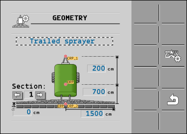
- On the main job computer: Distances between the main boom, the axle, and the attachment point.
- ▪
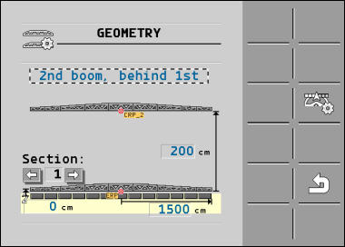
- On the auxiliary job computer: Distance between the main boom (CRP_2) and the auxiliary boom.
On systems with a one-sided folding auxiliary boom, you must also enter the distance DRP_Y:
- ▪
- The boom is located only on the left side: 0cm
- ▪
- Boom on the right side: Working width of the boom in cm
Procedure
To enter the sprayer geometry in the main job computer:
- þ
- You have set the second connector on the main job computer.
- ⇨
- There are two red dots on the diagram: CRP_1 - Attachment point; DRP - Axle; CRP_2 - Work point of the main boom. You must also measure the distance from this point to the second boom later.
- 2.
- On the line above the drawing, set the corresponding sprayer type.
- 3.
- Enter the measured values.
Procedure
To enter the sprayer geometry in the auxiliary job computer:
- ⇨
- The red dot CRP_2 marks the first boom.
- 2.
- On the line above the drawing, select whether the second boom is located in front of or behind the first boom (looking in the direction of travel): "2nd boom, behind the 1st" or "2nd boom, front of 1st"
- 3.
- Measure the distance between CRP_2 and the second boom (ERP) and enter this value.


 >
>  >
> 

