Information on the work screen
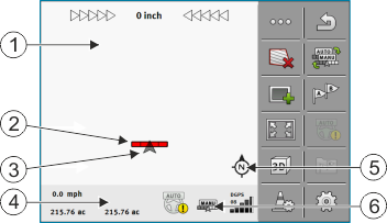
As soon as you start the navigation, the work screen appears. From here you can perform all other tasks which you will need during the field work.
The information shown on the work screen varies depending on whether SECTION-Control is activated.
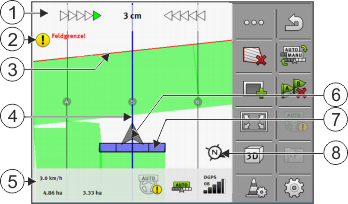
The next illustration shows you the other information on the work screen which can appear during work.
Work screen while working
To enlarge or reduce the view on the work screen, you can use the two-finger zoom function. If you only want to move the view, tap on any position on the screen and drag the view in the desired direction.
Moreover, you can centre the view on the work screen by tapping the compass.
If you see lines in the upper area of the screen, you can switch between the different views by swiping with your finger.
Guidance lines
Guidance lines are lines that help the driver keep parallel tracks.
There are three types of guidance line:
- ▪
- AB line - This is the first guidance line. It is always marked on the terminal screen with the letters A and B.
- ▪
- Activated guidance line – This is the guidance line that is currently being followed by the vehicle. It is marked in blue.
- ▪
- Not activated guidance lines – Guidance lines that are not activated.
When you have selected a guidance line set, you always see the currently selected set and the respective guidance line distance in the top area of the work screen.
Position of GPS receiver
The center of the gray arrow above the working bar corresponds to the position of the GPS receiver.
Working bar
The working bar symbolizes the agricultural implement. This consists of multiple rectangles. Each rectangle corresponds to a section. The color of the rectangle can change while working.
See also: Using SECTION-View
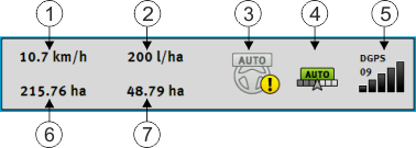
Counter and status information
In this area, you can see various information.
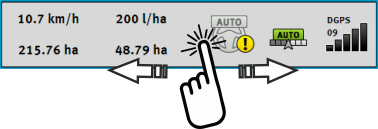
The circles in the bottom area of the screen show that you can switch between several displays:
- ⇨
- The next display appears.
Field boundary
The Field boundary tells the software the exact position of the field and is the base for calculating the total size of a field.
Traveled areas and areas where the product has been applied
The areas to the rear of the vehicle icon are marked in green. This green color can have any of the following meanings, depending on the configuration:
- ▪
- Traveled areas
- If you are only using TRACK-Leader, the traveled area is marked. This is marked regardless of whether or not the vehicle applied product during this travel.
- ▪
- Areas where product has been applied
- If you are using SECTION-Control, the areas where the product has been applied are marked. Surfaces over which the vehicle travels but where no product has been applied are therefore not marked.
If you want the software only to mark areas where the product has been applied in green, proceed as follows:
- ▪
- Activating SECTION-Control
or
- ▪
- Mount and activate the tool work position sensor
- The work position sensor detects if an agricultural device is in work position, and transmits this information to the terminal.
GPS connection status
Shows the status of the DGPS connection.
See also: Checking the DGPS signal quality


