Machine parameters
You will need the machine parameters in the following instances:
- ▪
- When you want to create a machine profile for a new machine
- ▪
- When you want to edit a machine profile
On the pages below you will find the explanation of all machine parameters.
Swath width
This parameter shows the working width set for an ag equipment.
No. of sections
Enter the number of sections that can be switched off on the implement. On a sprayer, they are the section valves; on a fertilizer spreader or a seeder, they can be half widths.
This parameter serves to transmit the proper number of sections to the SECTION-View module, so that you can switch the sections manually.
Each section appears as part of the working bar on the screen.
Sections
Opens a screen where you can enter the width of the individual sections on the implement.
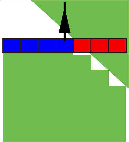
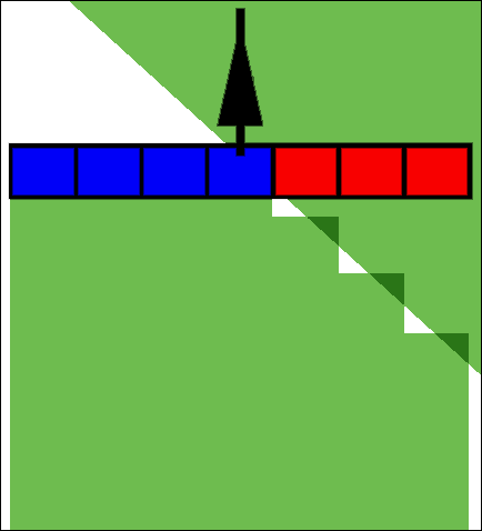
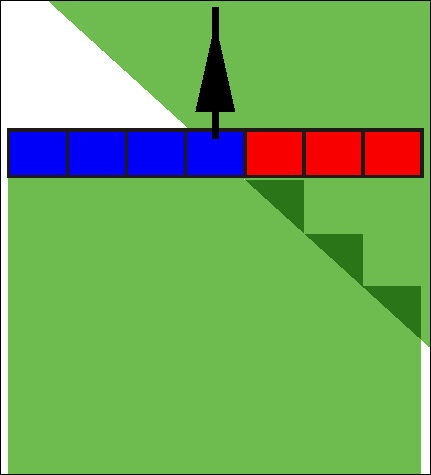
Degree of overlap
The degree of overlap when applying the product in a wedge-shaped area.
The set "Degree of overlap" is influenced at the outer sections by means of the "Tolerance of overlap" parameter.
Possible values:
- ▪
- 0% – When exiting a processed area, each section is only switched on when the vehicle has completely exited the area. When traveling onto a processed area, the section is only switched off when the section extends up to 1% over the processed area.
- ▪
- 50% – When exiting a processed area, each section is only switched on when 50% of the vehicle has exited the area. When traveling onto a processed area, the section is only switched off when the section extends up to 50% over the processed area. At a "Degree of overlap" of 50%, the "Tolerance of overlap" function has no effect.
- ▪
- 100% – When exiting a processed area, each section is only switched on when 1% of the vehicle has exited the area. When traveling onto a processed area, the section is only switched off when the section extends up to 100% over the processed area.
GPS receiver left/right
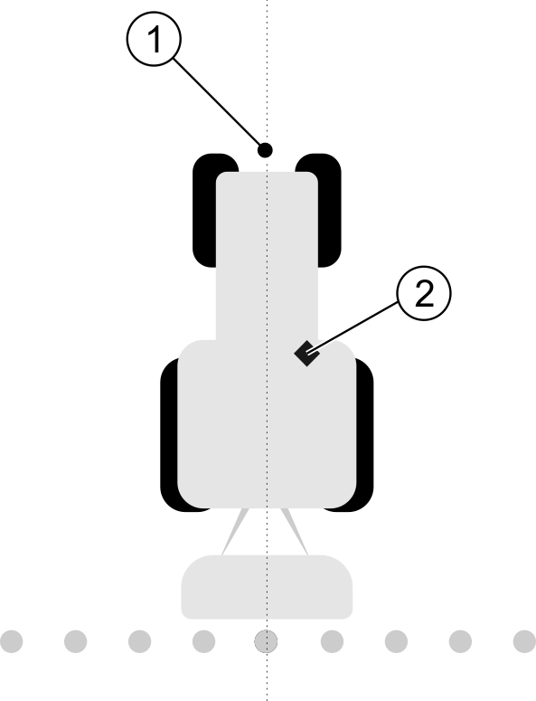
Here, enter the distance to the left or to the right from the longitudinal axis of the vehicle or tractor on which the GPS receiver is installed.
Position of the GPS receiver
The position of the GPS receiver which you have entered in the Tractor-ECU application will be ignored by TRACK-Leader if you use the machine profile. You must therefore ignore the values from the Tractor-ECU application at this point.
Possible values:
- ▪
- Enter a negative value, e.g.: - 0.20m
- if the GPS receiver is positioned to the left of the longitudinal axis.
- ▪
- Enter a positive value, e.g.: 0.20m
- If the GPS receiver is positioned to the right of the longitudinal axis.
GPS receiver front/rear
Distance of the GPS receiver from the application point. The treatment point may for example be the boom of a sprayer. For a fertilizer applicator, this is the spreader discs.
The position of the GPS receiver which you have entered in the Tractor-ECU application will be ignored by TRACK-Leader if you use the machine profile. You must therefore ignore the values from the Tractor-ECU application at this point.
Possible values:
- ▪
- Input a negative value, e.g.: - 4.00m
- if the GPS receiver is positioned to the rear of the application point.
- ▪
- Input a positive value, e.g.: 4.00m
- if the GPS receiver is positioned in front of the application point.
Operating position sensor
Is a tool operating position sensor mounted on the vehicle?
The tool operating position sensor is a sensor which recognizes that an agricultural device is set and delivers this information to the terminal. The sensor is available for many tractors and can be reached via the signal socket.
Possible values:
- ▪
- "Yes"
- ▪
- "No"
Inverted sensor logic
Is the sensor logic of the tool operating position sensor inverted?
- ▪
- "Yes" – Product application recording begins when the tool operating position sensor is not occupied. This will end when the operating position sensor has been occupied.
- ▪
- "No" – Product application recording begins when the tool operating position sensor is occupied. This will end when the operating position sensor is no longer occupied.
Machine model
This parameter determines the way and means in which the working bar should track the GPS receiver.
Possible values:
- ▪
- "self propelled"
- Settings for self-propelled agricultural equipment.
- ▪
- "trailed"
- Settings for agricultural equipment towed by a tractor.
- ▪
- "deactivated"
- Settings for mounted implements.
Screen light bar
Screen lightbar type.
Possible values:
- ▪
- "Deactivated"
- Deactivates the screen lightbar
- ▪
- "Graphic Mode"
- Activates screen lightbar in graphic mode
- ▪
- "Text mode"
- Activates screen lightbar in text mode
- ▪
- "SECTION-View"
- Activates SECTION-View
Implement type
Use this parameter to define the type of agricultural equipment.
The following implement types are available:
- ▪
- Sprayer
- ▪
- Fertilizer
- ▪
- Planter/Seeder
- ▪
- Harvester
- ▪
- Non specific system
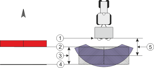
Spread pattern for a fertilizer
If you want to ensure precise application when moving on a headland or an application area, you can specify a spread pattern for your fertilizer.
Use the following parameter to define the spread pattern for a fertilizer:
- ▪
- "Spreading distance"
- This is the distance between the spreader discs and the center of the spread pattern.
- Spreading distance = (working length/2) + (distance between the switch-off line and spreader discs)
- ▪
- "Working length"
- Distance between the switch-off line and switch-on line in the spread pattern.
Procedure
This is what you have to do so that the parameters appear in the list:
- 1.
- Set the "Implement type" parameter to "Fertilizer".
- ⇨
- The "spreading distance" and "working length" parameters are displayed in the menu.
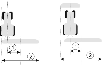
Implement offset
You can use this parameter to adjust the offset of the working width towards the left or the right. Enter the number of cm by which the center of the working width is shifted from the center of the tractor.
Possible values:
- ▪
- Enter a positive value, e.g.: 90cm
- If the equipment is offset to the right.
- ▪
- Enter a negative value, e.g.: -90cm
- If the equipment is offset to the left.
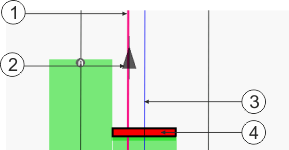
Mode of operation
If this parameter is allocated any value other than 0, the following occurs:
- ▪
- A red guidance line appears on the work screen, which is drawn at a distance from the blue guidance line.
- ▪
- The working bar is shifted to one side. The blue guidance line runs exactly in the middle.
After setting the implement offset, you have to operate the TRACK-Leader slightly differently:
- 1.
- Steer the vehicle such that the arrow is always following the red line. The center of the working bar then follows the blue guidance line.
Guidance lines for implements with offset


