Configuring SECTION-Control
In this configuration step, you will configure the section control for your ISOBUS job computer.
The application recognizes every ISOBUS job computer by means of its ISO-ID and sets up an individual profile for each of these. You can therefore configure different parameters for your fertilizer applicator and for your seeder or sprayer.
Procedure
- 2.
- Tap “Settings”.
- 3.
- Tap “SECTION-Control”.
- ⇨
- A list of the profiles for all ISOBUS job computers that have been connected to the terminal is shown. A new profile will be created whenever you connect a new ISOBUS job computer to the terminal.
- ⇨
- Virtual job computers from the Virtual ECU application also appear in this list.
- 4.
- Tap the name of the ISOBUS job computer for which you want to configure SECTION-Control. The connected job computer is marked with a green point.
- ⇨
- A list of the set parameters appears.
- 6.
- Change the parameters. You will find explanations of these on the following pages.
Parameters for SECTION-Control
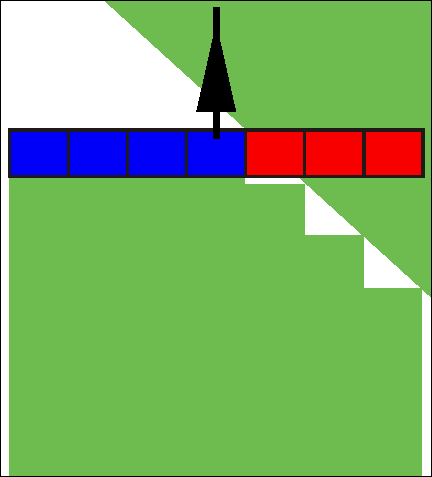
Degree of overlap
The degree of overlap when processing a wedge-shaped area.
The set “Degree of overlap” is influenced at the outer sections by means of the “Tolerance of overlap” parameter.
Possible values:
- ▪
- 0 % – When exiting an appliedarea, each section is only switched on when the vehicle has completely exited the area. When travelling across an area where the product has been applied, the section is first switched off when the section extends up to 1 % over the treated area.
- ▪
- 50 % – Each section is only switched on when exiting an area where the product has been applied, when 50 % of the vehicle has exited the area. When travelling across an area where the product has been applied, the section is first switched off when the section extends up to 50 % over the treated area. At a “Degree of overlap” of 50 %, the “Tolerance of overlap” function has no effect.
- ▪
- 100 % – Each section is only switched on when exiting an area where the product has been applied, when 1 % of the vehicle has exited the area. When travelling across an area where the product has been applied, the section is first switched off when the section extends up to 100 % over the treated area.
Tolerance of overlap
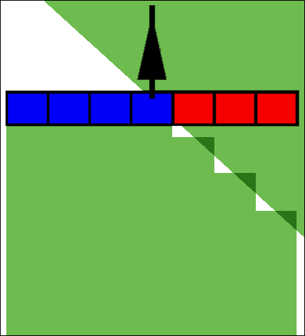
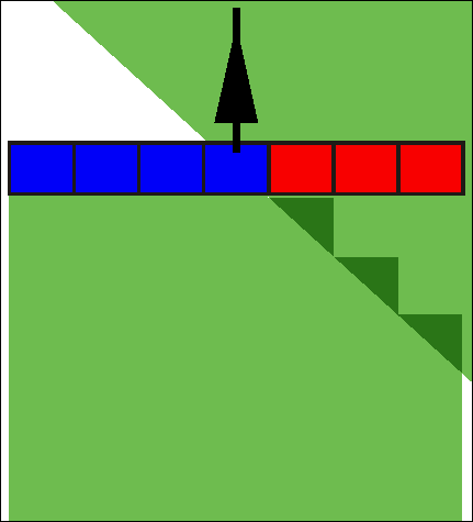
Use this parameter to define a permissible overlap. The outer sections are only activated when the overlap is greater than the value of this parameter.
The “Tolerance of overlap” only applies to the outermost left and right sections. No other sections are affected by this parameter.
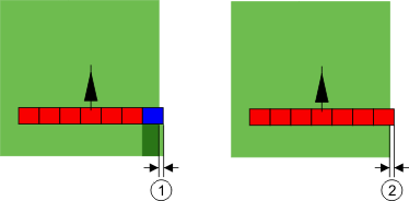
The following illustrations show how the “Tolerance of overlap” parameter acts with a “Degree of overlap” of 0 %. The set tolerance of overlap can be seen underneath the illustrations.
Tolerance of overlap for 0 % degree of overlap – in both cases the work was done with a 25 cm overlap.
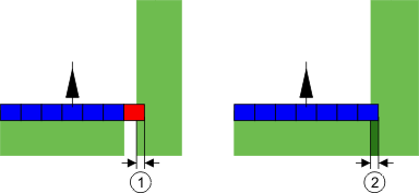
If you have set the “Degree of overlap” parameter to 100 %, the “Tolerance of overlap” parameter plays a vital role when leaving an area already processed. This is relevant for example when turning in headland which has already been processed.
Tolerance of overlap for 100 % degree of overlap – in both cases the applied area was exited by 25 cm.
Possible values:
Recommendation: If you are working with DGPS, the tolerance of overlap should not be less than 30 cm. For implements with wide sections, e g. with fertilizer spreaders, set the value accordingly high:
- ▪
- Tolerance 0 cm
- The outer section is switched off when it is located only minimally over an applied area. If it leaves this area only minimally, it is switched on again.
- ▪
- Other value
- The outermost section is switched on or off when the overlap exceeds the value.
- ▪
- Maximum value
- Half of the section width of the outermost section.
Field boundary overlap tolerance
Use this parameter to prevent sections from being activated at the field boundary in the event of a minimum overlap.
This parameter functions in the same way as “Tolerance of overlap”, but is only applied when the field boundary is exceeded.
Before making any change to this distance, make sure that this is safe for the environment and the surroundings under current circumstances.
Overlapping nozzles
This parameter is only applicable to sprayers with an individual nozzle switching function. This is not even displayed on other systems.
Use the parameter to set the number of nozzles which should operate in overlapping mode.
Delay
Delay is the period of time that elapses between the transmission of an order by the terminal and the implementation of the order by the implement.
This time can differ for each implement.
There are two parameters for the configuration:
- ▪
- Delay on start (when switching on)
- ▪
- Delay on stop (when switching off)
The values for both parameters are specified by the connected job computer per default and cannot be changed. These parameters are greyed-out and have the designation “Implement” in their names.
To adjust the delay times specified by the job computer, you can set the “Delay correction on start” and “Delay correction on stop” parameters. The values specified by the job computer are then offset against the values set on the terminal.
Notice
Correction of the delay times through the TRACK-Leader application is not available for all implement manufacturers. The delay times cannot be adjusted through the TRACK-Leader application for implements manufactured by HORSCH. Contact the manufacturer if you want to adjust the delay times for these implements.
Example
If a section of a sprayer passes over an area that was already processed, it must be immediately switched off. To do this, the software sends a signal to the section valve to switch off. This causes the valve to be shut off and the pressure in the hose drops. This lasts until there is no further flow from the nozzles. The duration is approx. 400 milliseconds.
As a result, the section applies an overlap for a period of 400 milliseconds.
In order to prevent this, the “Delay on stop” parameter must be set to 400 ms. Now, the signal is sent to the section valve 400 milliseconds earlier. As a result, the application can be interrupted or restarted at exactly the right moment.
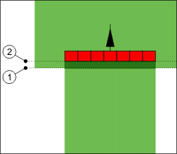
The illustration below shows how the delay function works. The illustration shows actual behaviour, not the indication on the screen.
Delay correction on stop was set to 0. A too brief delay time results in overlapping application.
Possible values:
- ▪
- “Delay correction on start”
- Enter the correction of the delay when switching a section on. If the section reacts too late to the switch-on signal, increase the value.
- e.g.
- –
- 400 ms solenoid valve manifold
- –
- 1200 ms electrically actuated valve manifold
- ▪
- “Delay correction on stop”
- Enter the correction of the delay when switching a section off. If the section reacts too late to the switch-off signal, increase the value.
- e.g.
- –
- 300 ms solenoid valve manifold
- –
- 1200 ms electrically actuated valve manifold
Machine model
This parameter determines the way and means in which the working bar should track the GPS receiver.
Possible values:
- ▪
- “mounted”
- Settings for mounted implements.
- ▪
- “Self-propelled”
- Settings for self-propelled implements.
- ▪
- “trailed”
- Settings for implements trailed by a tractor.
- ▪
- “Trailed and steered”
- Settings for trailed implements with drawbar or axle steering. E.g. for trailed sprayers with TRAIL-Control.
Screen lightbar
Screen lightbar type.
Possible values:
- ▪
- “Deactivated”
- Deactivates the screen lightbar
- ▪
- “Graphic Mode”
- Activates screen lightbar in graphic mode
- ▪
- “Text mode”
- Activates screen lightbar in text mode
- ▪
- “SECTION-View”
- Activates SECTION-View
Implement offset
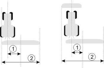
You can use this parameter to adjust the offset of the working width towards the left or the right. Enter the number of cm by which the center of the working width is shifted from the center of the tractor.
Possible values:
- ▪
- Enter a positive value, e.g.: 90 cm
- If the equipment is offset to the right.
- ▪
- Enter a negative value, e.g.: -90 cm
- If the equipment is offset to the left.
Mode of operation
If this parameter is allocated any value other than 0, the following occurs:
- ▪
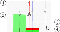
- A red guidance line appears on the work screen, which is drawn at a distance from the blue guidance line.
- ▪
- The working bar is shifted to one side. The blue guidance line runs exactly in the middle.
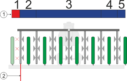
After setting the implement offset, you have to operate the TRACK-Leader slightly differently:
- 1.
- Steer the vehicle such that the arrow is always following the red line. The center of the working bar then follows the blue guidance line.
Guidance lines for implements with offset
Area of application
This parameter serves to adapt the behaviour of SECTION-Control for use with viticulture sprayers.
Section control on
Possible values:
- ▪
- “Standard” – Function is deactivated.
- ▪
- “Viticulture” – Function is activated.
Results
When the viticulture mode is activated, the behaviour of SECTION-Control changes:
- ▪
- If the angle between the guidance line and the vehicle is greater than 30°, the system assumes that the vehicle is turning. In this case, the application is terminated on all sections.
- ▪
- The “Field boundary overlap tolerance” parameter will be applied on all of the sections.
Minimal turning radius
To prevent the lines on the headland from crossing at an angle less than 90°, you can enter a radius here that can be driven by your vehicle with the mounted implement.
Distance from the field boundary
Safety distance from the field boundary. Implements are automatically always half a working width away from the field boundary. Depending on the entry, the safety distance is increased or decreased.
Reducing the line spacing
If you want to reduce the guidance line distance, enter the desired value here. The guidance line distance normally corresponds to the working width of the utilised implement.
You can see the current guidance line distance on the navigation screen.
Further information


 - Open the TRACK-Leader application.
 - Open the list of parameters.
 - As an option, you can also delete job computer profiles.